Polski
 English


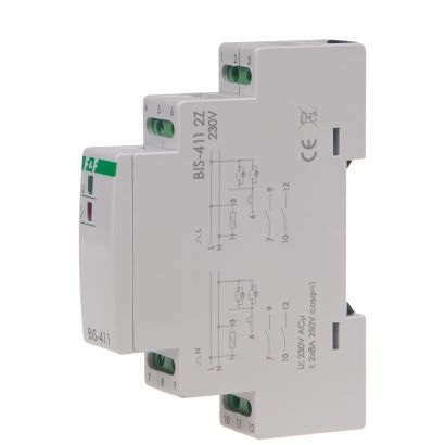
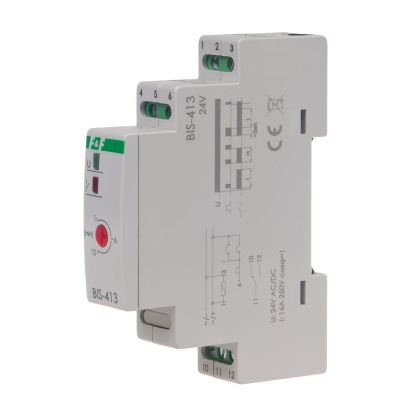
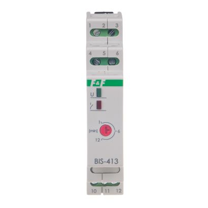
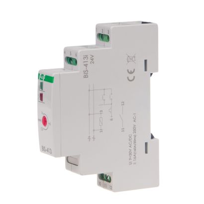
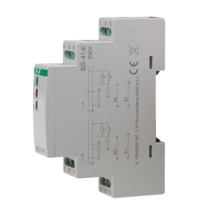
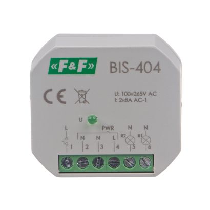
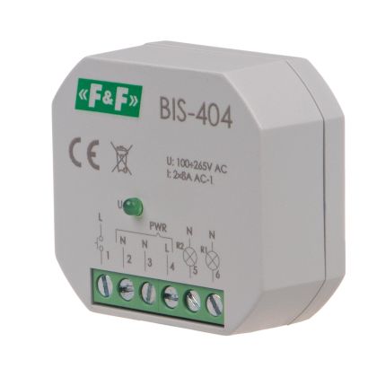
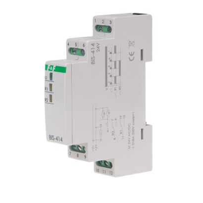
The relay have got two switch ON section and enable to switch ON in accordance sequence two circuits of lights or diferent recuiver from many places by pushbuttons connected in parallel. Switching the relay into another cycle phase is made by another current pulse triggered by pressing any bell push connected to the relay.
Functioning
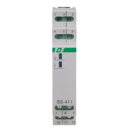
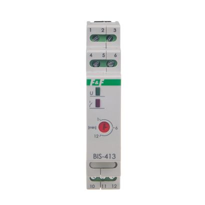
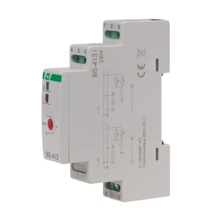
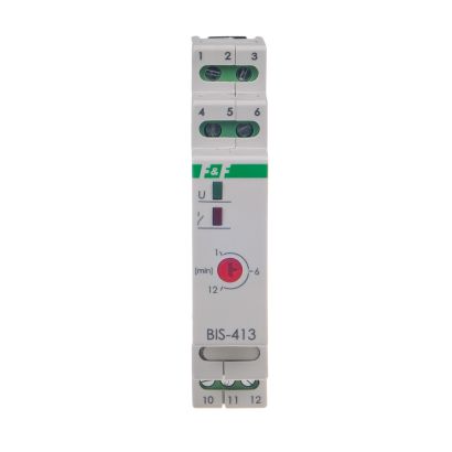
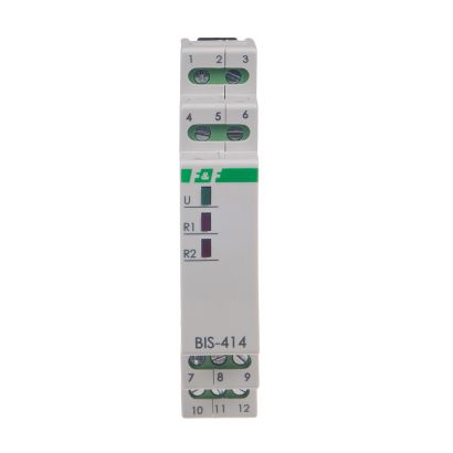
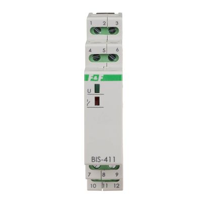
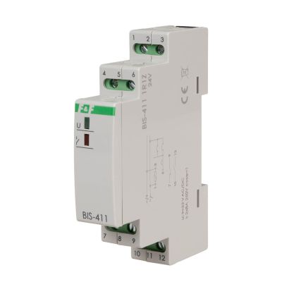
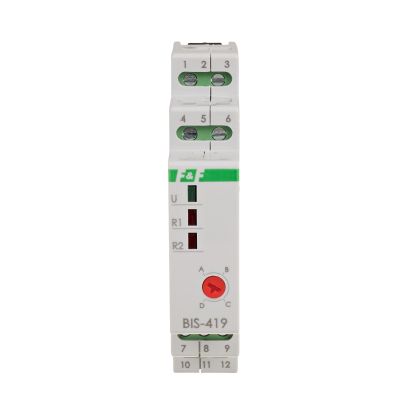
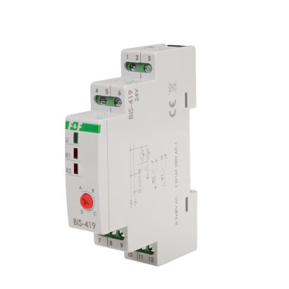
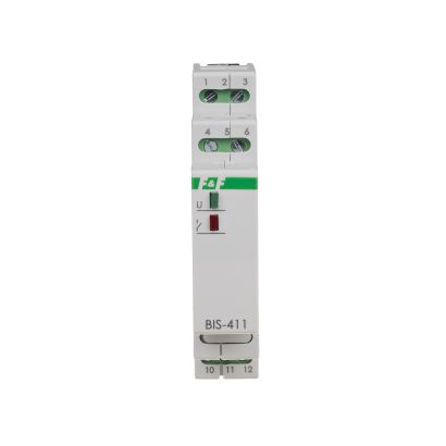
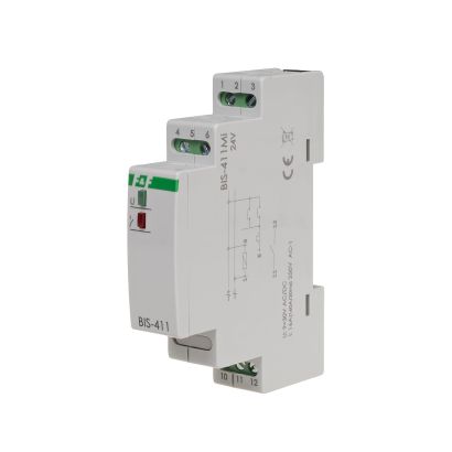
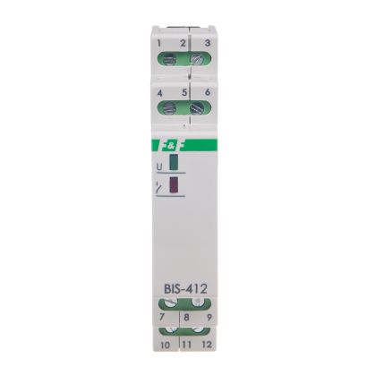
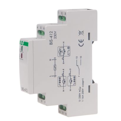
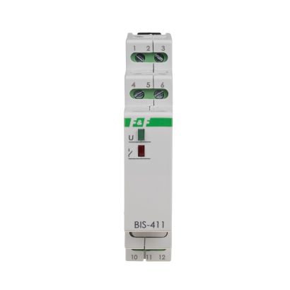
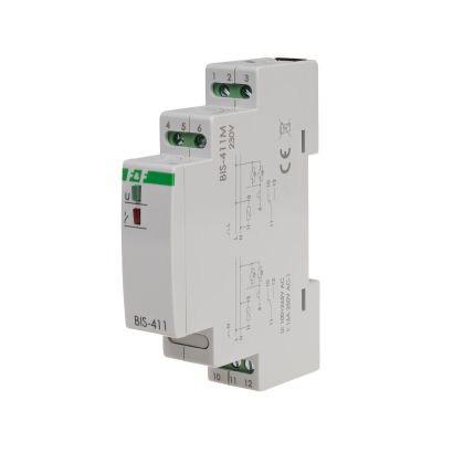
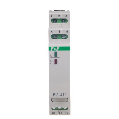
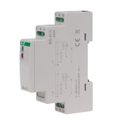
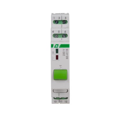
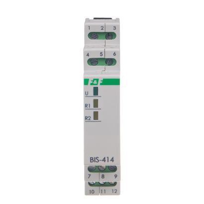
Relay power is indicated by a green LED U. Sequential relay has two separate outputs: R1 and R2. Contact state (open/closed) is forced sequentially in accordance with a predetermined program. State of contact is switched by a subsequent impulse from the the control key. Switching of R1 and R2 contacts is indicated by the corresponding R1 and R2 red LEDs. In case of a power failure, the contact state is reset. When the supply voltage returns, relay starts with a sequence number 0.
Power of receivers
These data are indicative and will heavily depend on the design of a specific receiver (that is especially important for LED bulbs, energy-saving lamps, electronic transformers and pulse power supply units), switching frequency and operating conditions.