Polski
 English


Features
* four independent outputs
* input designed to work with AC/DC signals
* state 1 trigger selection: with high or low voltage
* state 1 trigger selection: with closing or opening of the circuit input
* time filter that allows you to set the minimum acceptable length of input signal (elimination of distortions at the input)
Operation
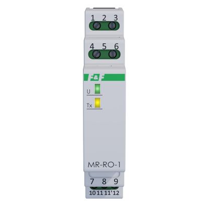
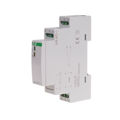
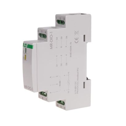
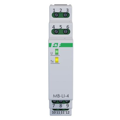
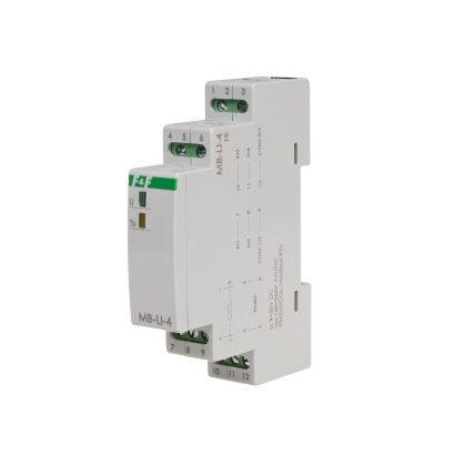
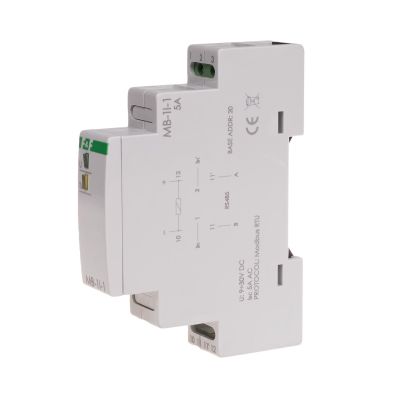
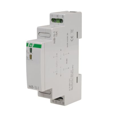
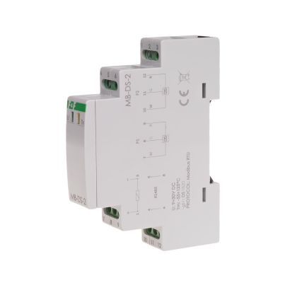
The MR-DI-4 module has four inputs. The module has configurable options for activating inputs (TRUE value) with low (0V) or high (V +) signal and with closing or opening the input signal circuit. Time filter is used for eliminating interference (false pulses) which may appear at the input. This is the setting of a minimum length of time of the input signal, which will be seen at the input and will be treated as a change of state. Shorter signals are ignored.
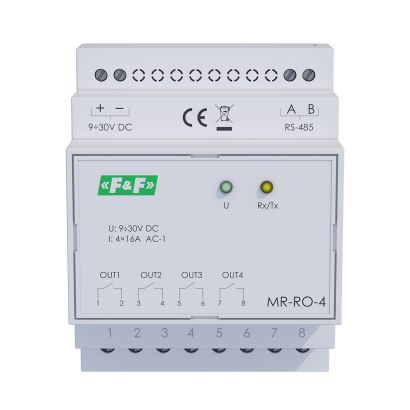
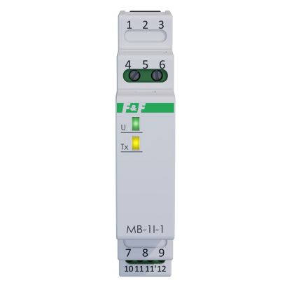
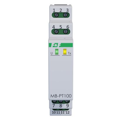
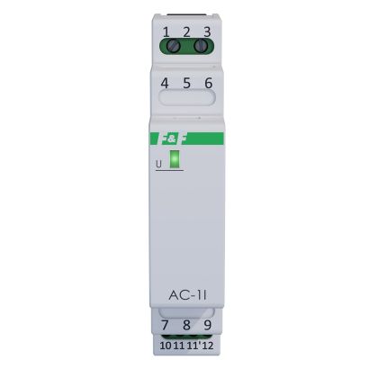
Reading of input states and adjustment of all communication and data exchange parameters is carried out via RS-485 port using MODBUS RTU communication protocol. Power is indicated by a green LED U light. Correct data exchange between the module and other device is indicated by the LED yellow Tx light.

 '
'
MODBUS RTU protocol parameters
Table of input triggering options and logical states assigned to them TRUE (1) i FALSE (0)