

Functioning
Working mode:
LAGGED DEACTIVATION(A)
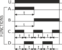
Until the relay is activated, the contact remains in the 10-11 position. After the power voltage is supplied (green LED U is shining), contact is shifted to position 10-12 and the countdown of the preset value „t” is commenced (red LED is shining). After the preset time „t” has been counted down, contact returns to position 10-11. The working sequence of the relay may be repeated after turning the power supply off and on.
LAGGED ACTIVATION (B)
After the power voltage is supplied (green LED U is shining), the contact remains in position 10-11 and the timing of the preset value t is commenced. After the preset time t has been counted down, the contact is shifted to position 10-12 (red LED is shining). The working sequence of the relay maybe repeated after turning the power supply off and on.
LAGGED ACTIVATION - CYCLIC (D)
The Lagged Activation mode is triggered in equal work cycles according to the preset time values.
LAGGED DEACTIVATION - CYCLIC (C)
The Lagged Deactivatin mode is triggered in equal work cycles according to the preset time values.

Attention!
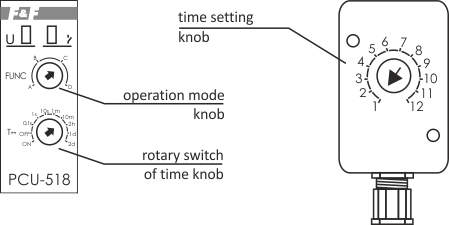
Setting the time range knob regulator in the:
- ON - position with power supply activated connection of contact in position 10-12.
- OFF - position with power supply activated connection of contact in position 10-11.

