

Functioning
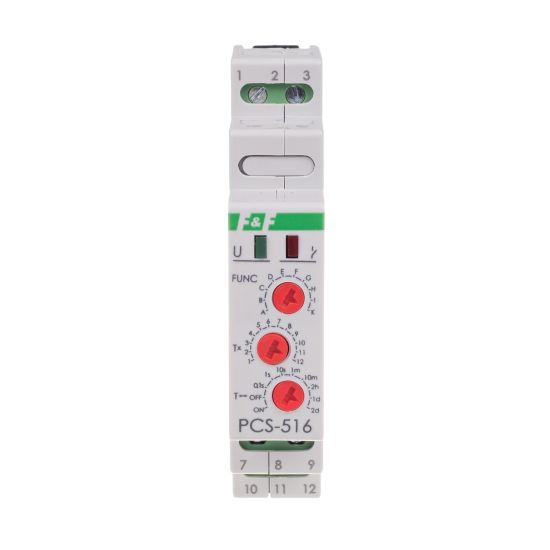
The relay performs a function selected in accordance with the regime set period. The choice of a specific range of time and work the relay function is to set the appropriate combination of rotary coded switches.
A. ON delay
After the supply voltage is switched on (the green LED U is on), the contact remains in position 11-10 and the set operating time counts down. After the preset time has elapsed, the contact switches to position 11-12 (the red LED is on). To execute the operating mode of the relay again you need to switch off the power supply voltage and switch it back on.
B. OFF delay
The contact remains in position 11-10 until the relay is switched on. After the supply voltage is switched on (the green LED U is on), the contact is switched in position 11-12 and the set operating time t is measured (the red LED is on). To execute the operating mode of the relay again you need to switch off the power supply voltage and switch it back on.
C. ON delay – cyclic
On delay operating mode is carried out cyclically at equal intervals between the preset operating time and break time.
D. OFF delay – cyclic
Off delay operating mode is carried out cyclically at equal intervals between the preset operating time and break time.
E.
Generating pulse 0.5 s after the preset time t.
F.
Generating a single pulse with time t by the rising edge of the start signal. During the time measurement, the system does not react to start pulses.
G.
Generating a single pulse with time t by the trailing edge of the start signal. During the time measurement, the system does not react to start pulses.
H.
Off delay with back-up feature The rising edge of the start signal causes the relay to be switched on, while the trailing edge causes the start of time measurement. Applying the start signal during the time measurement causes the cycle to be extended by another time t with the trailing edge.
I.
Generating a single pulse 0.5 s after time t with the triggered trailing edge of the start signal.
K.
Switching off the relay for a specific time t with the rising edge of the start signal. During the time measurement, the system does not react to start signal.
Attention!
*Setting the time range knob regulator in the:
ON - position with power supply activated results in the permanent closure of the contact in position 3-7 (UNI) and 11-12 (DUO).
OFF - position (power supply activated) causes the contact to be permanently closed in the position 3-5 (UNI) and 11-10 (DUO).
*With the power supply on, the system does not respond to the modification of time range and operation mode.
*The newly set time range and operation mode values are active after the power supply is turned off and on or after the RESET voltage is supplied.
* With the power supply on, it is possible to regulate the preset time freely within the selected time range.
*If the function is changed into F, G, H, I, or J, one with the power supply on, and the START voltage is supplied, the system will carry out the previous function and then reset (switch into the newly selected function). A further instance of the START voltage supply will result in executing the new function.

